Oscillations and Waves: Winter-2026
HW 3a: Due W3 D3
- Q factor of a Resonance Circuit
We define a “quality factor”, \(Q\equiv\frac{\omega_0}{2\beta}\), and use it as a measure of cycles in a free (undriven), damped oscillator before the oscillation decays to some smaller amplitude. The larger the number of cycles, the larger the \(Q\). Now let's see what this quantity translates to in a driven, damped oscillator. Use the example of charge amplitude\(|q|\) for a series LRC circuit.
Show that at both frequencies \(\omega=\omega_0 +\beta\) and \(\omega=\omega_0-\beta\), the magnitude of the charge response \(|q|\) is \(\frac{|q|_{max}}{\sqrt{2}}\).
(Hint -- You don't need the definition of \(|q|\) in terms of \(L,\,R,\,C\)).At these frequencies, how large is the energy in the capacitor compared to the maximal energy at \(\omega\approx\omega_0\)?
- Given the above, operationally, how would you measure the \(Q\) of a resonant circuit? What is \(Q\) for your circuit?
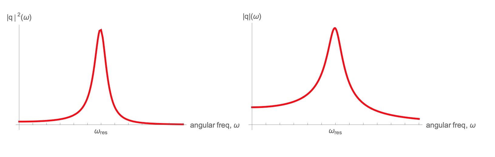
The graphs below may help with a visual feel for the quantities discussed above:
- Steady State Solutions for the LRC Circuit
Write the equation of motion governing the charge on the capacitor in a series LRC circuit driven by an external sinusoidal voltage. Identify all parameters in your equation.
Find a steady-state solution (or particular solution) for the current in the circuit. After what time is the steady state the only relevant part of the solution, i.e., after what time has the transient solution decayed for the circuit you are working with?
- Find the steady state solution for \(\frac{dI}{dt}\) in this circuit.